- 烈焰私服


Onboard JFET Preamp
-

Switches S1 (Mid Cut) and S2 (Mute) are optional. Feel free to experiment with different values for C3 and C4.
For measuring JFETs please refer to the .

I use this preamp for my acoustic bass to mix two piezo pickups (Underwood/Realist). For this purpose, I changed P1 and P2 to 2M5. First impression: The mid cut function is too strong/not necessary for double bass, and the pickups are out of phase. Thinking about a phase switch. No problems otherwise, works great.
(Click on the schematic for a larger version)
FAQ:(submit your question here)

Schematic (GIF 13k)
Notes:The source resistors R2, R5 and R11 have to be selected according to the FET (and the supply voltage). Connect a 5k pot instead of the source resistor and adjust for maximum non-clipping signal at the drain. Then disconnect the pot, measure its resistance and put a resistor with the closest value available into the circuit.
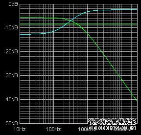
Pictures:Here are the frequency characteristics of the tone control (simulated with Duncan Munro's Tone Stack Calculator). The curves represent the left/center/right positions of the tone control:
Frequency with S1 switched (C3=1n, C4=3n3)Version 1.0 (07/03/2002)


PCB (GIF 5k)
The circuit has an overall gain of +6dB. To increase gain, reduce the value of R12. If you omit R12/C5, you get approx. 0dB (unity gain).
Pictures of the prototype. I use it on my double bass for mixing two piezo pickups (Underwood and Realist). For this purpose I changed P1 and P2 to 2M5:
Components Layout (GIF 11k)
Description
After the unexpectedly big success of my JFET bass preamp I decided to build an onboard version. For a Jazz Bass-like instrument, I had to get along with three controls, maybe some switches if I used push-pull pots. Further, I wanted the functions of the knobs unchanged (vol - vol - tone) and, if possible, use the original pots.
Email
Frequency with S1 as shown (C3=1n+2n2, C4=3n3)
This preamp features independent buffer stages for both pickups, a "Big Muff" style tone control with switchable mid cut and a gain/buffer stage for the output.
The PCB is 2" x 7/10" (5.1 cm x 1.8 cm) in size. The holes fit to a grid of 1/10" (2.54mm). You should get the right size if you print it out with 300dpi.
,